
If you’re using a term that you cannot define adequately, then you should drop that term entirely; it cannot help you and will only create confusion later on. Find a better concept.
Read MoreExample Map – the Simple Requirements Model
What makes a map of System Engineering valuable? How does a system engineer use a map to get from one place to another in the engineering process? How does a map support decision making?
In a previous article, I addressed what it takes to build a map of the Systems Engineering territory, or an information schema for SE data. I included a real map of a schema created for a tool back in the ancient days of the 1990’s. That map was far too complicated to explore for an introductory discussion, so I put together a very simple map of systems engineering that I expect many SEs can understand and agree to, at least in principle. I’ll call it the “Simple Requirements Model”, or just SRM.
In the rest of the article I’ll explore the SRM to establish some basic concepts about managing maps of information for systems engineering.
The Simple Requirements Model (SRM)
Entities
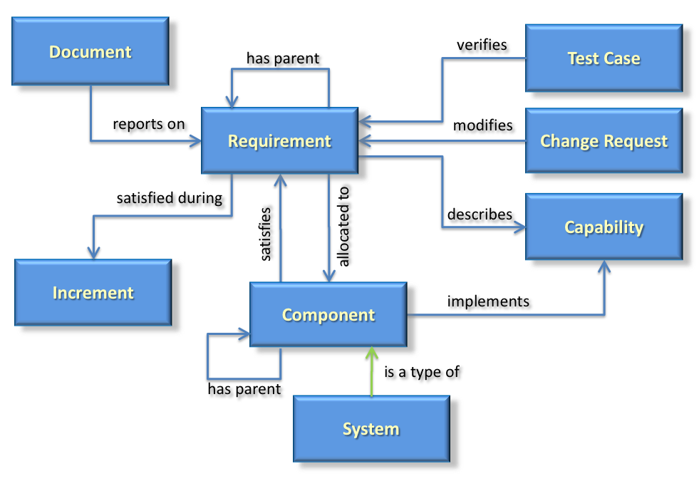
The model graphically shows entities using blue rectangles. Each entity is a collection of tightly coupled data which collectively define the entity, and uniquely identify that entity. If you are an aficionado of relational databases, you might think of these entities as rows in a table. If you’re an advocate of object-oriented methods, you might consider the entities to be objects that realize a particular class. For this high-level discussion, the specific implementation is irrelevant.
Entities also have a set of business rules, which are unique to the type of entity. The rules define processes for creating an entity, establishing entity validity, how to perform configuration management for the entity, and others. The business rules are not visible in the entity data; instead the business rules define the processes and operations behind the entities. Business rules will be unique to the organization that creates the system engineering map. For this introductory level discussion, the business rules are kept to a minimum.
Relationships
Entities have relationships between one another shown by lines with arrowheads to indicate directionality of the relationship. Relationships show that entities have a correlation or linkage between them. To capture the meaning of that linkage, every relationship needs at least a name to define it, and rules for how the linkage is made.
Consider your relationship to an automobile. You might be the driver of the car which is established when you get into the drivers seat, start it and drive it off. You might very well also be the owner of the car, which is established by the title to the car and kept by a local government entity. You and the car are two very different entities, and have two (or more) very different relationships.
Exploring the Map
Now that we have some basics, let’s look at the SRM map in more detail.
As described above, a well-constructed map of an information territory, or domain, represents well-defined entities with not only a name and perhaps a descriptive definition, but also with a set of attributes necessary to characterize the entity in the particular context. Each of the elements in the SRM needs its own set of attributes. Let’s explore the entity at the center of the SRM, the requirement.
So what is a requirement? According to INCOSE, a requirement is:
-
A condition or capability needed by a user to solve a problem or achieve an objective.
-
A condition or capability that must be met or possessed by a system or system component to satisfy a contract, standard, specification, or other formally imposed documents.
-
A documented representation of a condition or capability as in (1) or (2)
For our purposes, a requirement is most closely like definition 3, the documented representation of 1 and 2. Since it is a defined element of this model, we shall refer to the entity as a «requirement», where the guillemets («») act as a flag that we are talking about a well-defined element of the SRM.
(If you choose to use an indicator of a defined entity in your documentation, you can choose any indicator you like, or no indicator at all. I advocate flagging any reference that has a well-defined meaning to let readers know they’re looking at something using a precise definition, and not a random or ambiguous term.)
Not only does the «requirement» have a definition, it is also characterized by a specific set of attributes that describe the «requirement» and only the «requirement». Here is a look at the attributes of a «requirement» in the SRM:
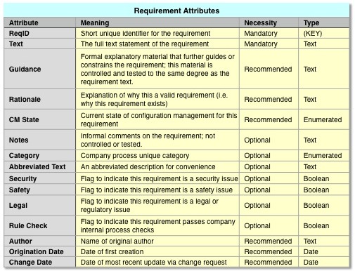
Attributes for a «Requirement» in the SRM
In the context of the SRM (and frankly, in almost all practical contexts) a «requirement» can be characterized with only two required attributes, a unique ID and the text of the user need. (SysML defines exactly these two.) In the SRM there are only 15 requirement attributes defined, and only two are mandatory.
Since the «requirement» entity is at the center of the SRM domain, the next step will be to see how it relates to the other entities in the SRM.
«Requirement» «has parent» «Requirement» Relationship
A set of «requirement»s tends to have a hierarchical organization, so a «requirement» can have a relationship to another «requirement» called its parent, or «has parent». The relationship is shown with a directed arrow. The hierarchy can be discerned by recursively following «has parent» relationships until we find a «requirement» that has no parent «requirement»s.
in a more complex model, the «has parent» relationship might be replaced or complemented with more detailed relationships, such as «decomposes», «disambiguates», or «derived from». The SRM uses the simpler «has parent» relationship.
«Document» «reports on» «Requirement» Relationship
A hierarchical set of requirements is usually represented not in a simple list, but in a document or specification. A «document» is a separate entity from a requirement because a document has a different set of characteristics. Documents will have a formal ID, title, author, revision, multiple sections and subsections and release sensitivity. None of these apply to individual requirements. It makes sense then that a «document» should be stored as a separate entity from a requirement.
This is significantly different from legacy DOORS 9.x implementations, in which requirements and documents are misguidedly mixed together into a confusing morass. (It is possible to separate the two using DOORS 9.x, but that requires the design of the database to differ from the originally intended design of the DOORS application.)
Furthermore, «document»s differ from «requirement»s because «document»s have different methods to operate on and maintain them. Instead, «document» «report on» «requirement»s, or inversely, «requirement»s are «reported on» by «document»s.
Publishing a specification is a process of selecting the «requirement»s from a model based on a query of the requirement allocation to a component, and then building a «document» to organize and report on the selected «requirement»s.
«Requirement» «allocated to» / «satisfies» «Component» Relationships
A «requirement» states what the customer needs, but that need is delivered as a «component» of the overall deliverable system. This is how the SRM ties together the descriptive model of «requirement»s with the structural architecture model of «component»s. A typical business rule maintains that a «requirement» is allocated to exactly one «component». (If it were allocated to more than one, then the «requirement» would be stating more than one goal and needs to be decomposed into multiple requirements.) The inverse relationship says that a «component» satisfies a «requirement». A «component» can satisfy multiple «requirement»s.
A «component» is a separate entity from a «requirement» because it has unique characteristics that describe it as a physical entity. «Component»s will have a unique identifier, a set of functions, a set of constraints, physical characteristics that describe it as a controllable physical item, procurement attributes and others. In addition, «component»s are managed and controlled as configuration items, not as «requirement»s.
«Component» «has parent» «Component» Relationship
The architecture of a system generally is a hierarchical structure of «component»s. Similar to a «requirement», a «component» has a relationship to a parent «component» via the «has-parent» relationship. Traversing the «has-parent» relationship reveals the structural hierarchy.
«System» «is a type of» «Component» Relationship
In the SRM, «requirement»s are «allocated to» «component»s, which allows some flexibility in how a business defines a «component». Since I’m describing a system engineering model, the model needs to have a «system» in it. In the SRM, I show that a «system» is a specific kind of «component» using the relationship «is a type of». In a larger and more useful SE model, the «system» and «component» would have a much more detailed model surrounding them and describing more relationships.
«Requirement» «satisfied during» «Increment» Relationship
In many projects, the development effort will be spread over several phases, or implemented in «increments». A business rule might state that a «requirement» will be «satisfied during» exactly one increment. (If it were «satisfied during» more than one, then the «requirement» would be stating more than one goal and needs to be decomposed into multiple requirements.)
«Test Case» «verifies» «Requirement» Relationship
In order to prove that a «requirement» is met, the «requirement» needs to be tested and verified. A «test case» defines the testing and verification approach and is related to multiple «requirement»s through the «verifies» relationship. A «test case» is a unique entity from a «requirement» not only because it has unique descriptions and goals, but is finalized during a later lifecycle phase of the program, generally after the requirements set has been baselined.
«Change Request» «modifies» «Requirement» Relationship
In order to control changes to a requirements set in an orderly fashion, each «requirement» is generally placed under control of configuration management. A business rule might state that a «change request» is necessary before modifying a «requirement». The «change request» might have attributes that look a lot like the attributes of a «requirement», as well as additional attributes for status and tracking of the request. The «change request» is handled differently from a «requirement» and lacks the other relations of a «requirement». Given these factors, the «change request» is an independent entity in the SRM.
«Requirement» «describes» «Capability» Relationship
A «requirement» states what the customer needs, but ultimately the customer has a specific desired effect the customer wants to see in the end product. That desired effect is captured by a «capability» entity. Typically multiple «requirement»s will «describe» a «capability». This is how the SRM ties together the descriptive model of requirements with the results-driven behavioral model of «capability»s.
«Component» «implements» «Capability» Relationship
Finally, the «components»s of the end product must exhibit well-defined, desired behavior to satisfy the customer. The SRM models this by showing that a «component» «implements» one or more «capability»s. A business rule might allow a «component» to «implement» many «capability»s, but insists that a «capability» be implemented by exactly one «component». (If a «capability» were implemented by multiple «component»s, then the «capability» would need to be decomposed into multiple subcapabilities. The SRM, being simple, does not support this.)
Map Making Lessons
This map is so simple the reader no doubt found multiple deficiencies and inconsistencies between this simple model and their own company’s system engineering approach. Still, this simple example provides a background to learn a few lessons.
One of the first lessons learned is that creating this very simple map, or schema, is a surprisingly tedious process. It was probably even tedious to read it. (Sorry about about that.)
Part of what makes it so tedious is that we feel we already know these entities and relationships. If we knew them so well, they would be written down, wouldn’t they? If everybody knew them by the same exact definition, wouldn’t the system engineering process go much faster and be more accurate? Despite feeling that we know them, almost no one has really taken the time to be explicit with them. (I’m sure a Vitech Core sales representative will chime in here. Feel free to comment.) As a result, when moving from company to company, and even project to project, we waste a lot of time reinterpreting our map for the SE process, and stumbling over minor misconceptions and terminology. SE is a discipline of communication and information management, yet we fail to do that for ourselves.
If your company actually goes to this level of detail, or more, please let me know in the comments. I only encountered one organization in my 35 year career that actually gave this much thought to the engineering process.
Another humorous lesson is that using guillemots is itself tedious, especially in an article that references the underlying entities of a model a lot!
And we’re not done yet. The next lesson to be learned is captured in the final installment of information management in systems engineering. I’ll explore how to use the SRM to satisfy the needs of engineering users.
DISCLAIMER: I am tool agnostic. I am not associated with any tool or vendor, nor do I benefit from any tool sales or stock.
(part 4 coming soon)
Learn when the latest articles in this series are posted – Join the vmcse.com mailing list because you don’t want to miss out.
Building a Map for System Engineering
 In order to better perform our jobs as system engineers, we need to understand the territory of systems engineering, guide ourselves from point A to point B in that territory, and be able to communicate our results to our stakeholders. We understand our jobs by building and following a metaphorical map of the system engineering territory. We make decisions about how to get from one point to another. We communicate to our customers by providing them another simplified map of the results that they can understand and relate to. (Yes, the PowerPoint graphics so commonly used are a method of describing maps.)
You’re probably wondering why I discuss metaphorical maps and not the specific details of the system engineering process. The reason is simple. Often we’re stuck in a very specific way of thinking. An intellectual rut, if you will. We’re locked into specific interpretations of our jobs and processes. By thinking metaphorically, sometimes we can see relationships and open up to ideas we wouldn’t see without the metaphorical view. If you’re willing, let’s explore this metaphor together. Let’s back up, and ask ourselves, what is a map in general?
What is a Map?
For once, the dictionary fails us by not providing a good definition of map, so instead we turn to Wikipedia, where we learn that a map is:
[su_quote]…a symbolic depiction highlighting relationships between elements of some space, such as objects, regions and themes.[/su_quote]
In a typical road map, as you might see on Google Maps, Bing, Apple Maps, or Waze (or many others) we see geographic regions and their relationships. Some of the information includes relationships between cities via roads and relative locations. We also see municipal boundaries and geopolitical extents. We can see the relationships between cities and geographic entities such as rivers, lakes, mountains and shorelines. Using more detailed views, we can delve down to the relationships between individual addresses and the corresponding cities and roads.
Of course, there are many different kinds of maps. Maps have a specific scope and purpose, a specific theme. Geographical, or topographical, maps are the most commonly used, but there are also many others. Aeronautical maps that show airspace restrictions, radio frequencies and general aviation information. Topological maps show relationships and connections, but no extraneous information (such as scale or distance) depending on the application. Network maps show interconnectivity among communications nodes. There are too many types of maps to mention here, but the interested reader can look into the subject of cartography on Wikipedia.
Given all the information on the maps, what do maps do for you?
- Provide information to find where you are, whether it be a city address or a network node (navigation)
- Describe the lay of the land
- Show terrain, entities, and relative placement of the entities whether city addresses or network nodes
- Show important llandmarks
- Show entities of interest for the subject area
- Enable guidance
- Provide information needed to decide how to get from one node to another
- Allow you to find the best routes
There are things that maps do not do. For example, a map can enable guidance on your available travel options, but the map cannot tell you how to get from point A to point B. Should you travel by car, or by airplane? The map cannot answer that. Should you detour to visit an attraction, or drive straight through? The map cannot make decisions for you. The map, by itself, cannot tell you the process of getting from A to B, nor the decisions along the way. It only provides the information necessary to enable the decisions. Without the information, you can’t make the decisions necessary to follow your process.
To cross terrain, we need both a map and a process for making travel decisions. The common GPS system in your car or on your phone is a combination of a map, and an application to handle decision making. In this case, the decision making is restricted to particular assumptions, such as travel by automobile, and that the goal is either the shortest distance or quickest route.
If you think about it, a map comes pretty close to fulfilling my definition of a model:
- it’s a visual representation
- it’s a pattern of something else, which already exists in this case
- it captures information on structure, data and inferences
- often it is formalized, as in the case of GPS systems which store the map info in a database
Maps and Processes
System engineering is generally considered a set of processes with goals. The main goal is to move from customer concept to design specification that can be handed off to other disciplines, like moving from one map point to another. Where’s the information necessary to decide how to move? We describe our processes in System Engineering Management Plans (SEMPs) and measure our compliance to our processes, but we very poorly formalize the necessary information. I believe the missing ingredient is the map of the SE landscape that provides the information for the necessary decision-making.
In my opinion, system engineers have spent decades developing processes, but far too little time developing and formalizing the map of the SE territory. In order to make decisions, we need a complete model of the system engineering territory, including a model of the SE discipline itself and a model of the customer needs.
When building models and maps of decision-making processes, we start to venture into the realm of Enterprise Architecture, or EA. For the purposes of this article, I’ll avoid any Enterprise Architecture specific terms. My views on EA will be discussed in another article.
The system engineering territory does not need to be explored like a poorly known Louisiana Purchase by the Lewis and Clark Expedition. (A part of early United States expansion in 1804-1806.) We’ve already covered the SE territory, but we haven’t documented it very well. There have been maps of SE, like the image bellow of the schema from an old SE tool in the 1990’s, so the knowledge is there. We just haven’t made that knowledge persistent.
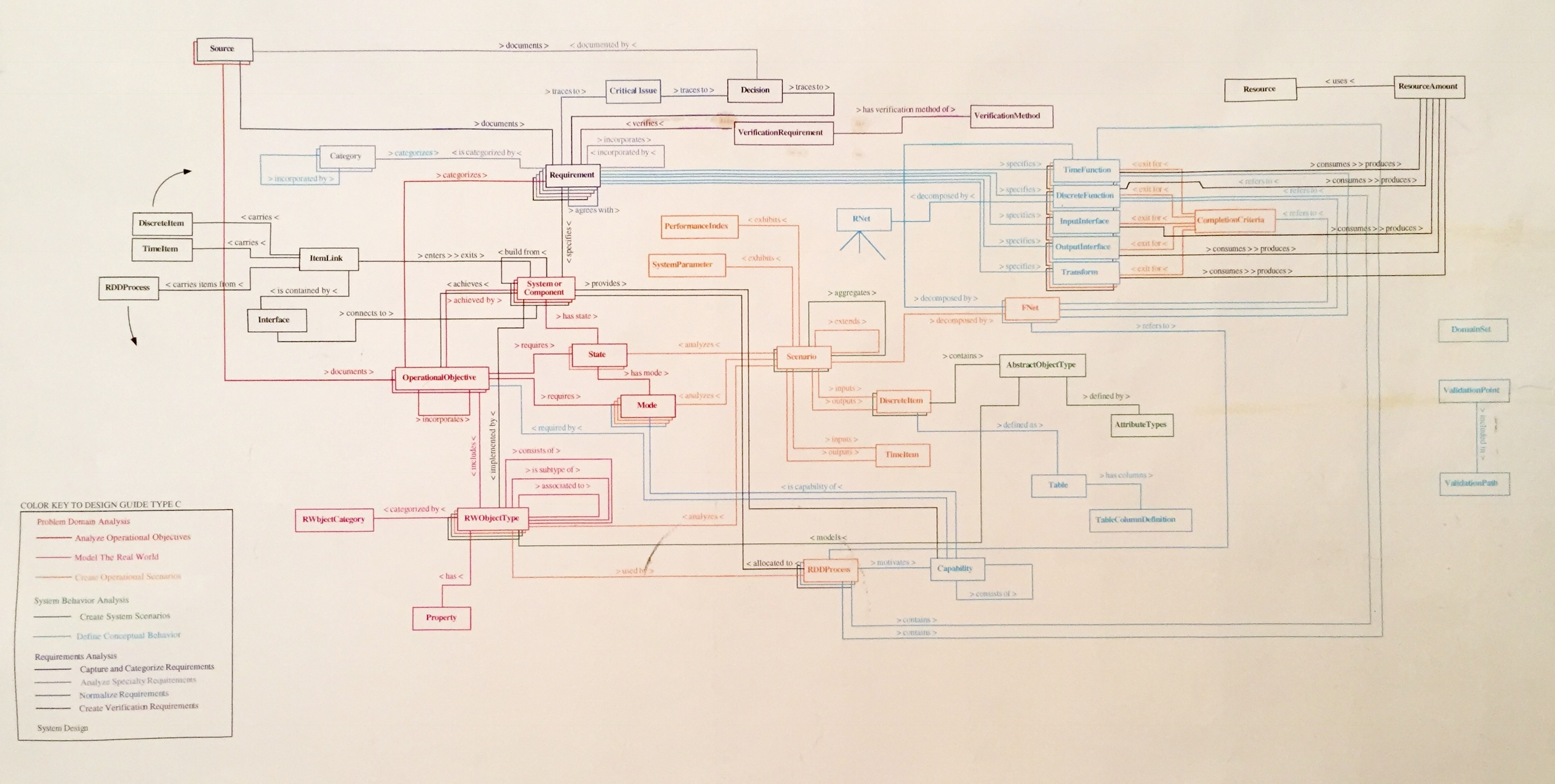
This particular map is of “Design Guide C” from the tool RDD-100 by Ascent Logic, Inc. Oddly enough, the design guide (1 of 4 maps) was only documented in an alphabetically organized reference guide; this visual diagram was never provided by the vendor. The picture only exists because I spent several days back in the 90’s exploring the reference guide to divine these visual relationships.
I believe that understanding the basic system engineering entities and their relationships is the key to improving the entire process of system engineering, and the solutions we generate. In the next article, I’ll look at a simplified “map” of system engineering and what needs to be done to make it useful.
Learn when the latest articles in this series are posted – Join the vmcse.com mailing list
The Information Side of System Engineering
First in a series
The Role of Information in System Engineering
 As system engineers, we like to think that our jobs are to engineer at a system level, that is, we “enable the realization of successful systems” as INCOSE would say. In order to do this, we address customer needs, operations, performance, cost and schedule, training and support, and to a lesser degree, test, manufacturing and disposal. These are all very important areas to address if the system is to be successful. If the system is to meet user needs, a discipline that coordinates and integrates these other disciplines is essential, hence system engineering.
System engineering is not a discipline of design. We don’t design integrated circuits or printed circuit boards. We don’t solder components to PCBs. We don’t write production C++ or Java code. We don’t install blade servers into racks and connect them with a specific network topology. We don’t design mechanical parts to be machined on a Computerized Numerical Control (CNC) milling machine. We don’t really do the “fun” stuff in engineering.
Instead system engineers have their own tasks. We gather the user needs and wants, formalize them into requirements and create a requirements database. When in doubt about a user need, we perform trade studies to determine the best implementable option, and document that in a trade study report. We define the concepts of operation, system functions and logical architecture. We record all that in a set of specs and architecture documents, or better yet, in an MBSE database. We create mappings between all the entities we defined and try to document those linkages.
Show Me the Data
This is nowhere nearly a comprehensive list of what system engineer do, but there should be a pattern emerging. System engineers tend to create documents, databases, spreadsheets, relationships and all varieties of information. SE doesn’t produce deliverable system end-products; no software, no hardware, no electronics. Instead, system engineering produces intermediate products. System engineering gathers and synthesizes the information necessary to design and build a product to satisfy the customer. The individual disciplines actually build the product. System engineers answer the critical questions the other disciplines need to know up front to do their jobs right. System engineering is a discipline of gathering and synthesizing information then presenting it in such as way that it can be understood and used for communications both to the development disciplines and also to the customer. System engineering is a discipline of information and coordination.
I am not the first to observe this. Other authors have opined that system engineering is really an exercise of information management. (I’d credit them if I could remember who inspired these ideas. If you know of anyone who also talks about this, please let me know so I can reference them and give due credit.)
Lately some educational institutions have issued degrees in system engineering, but in general we’re usually electrical or software engineers who transition into the field. Sometimes we are specialized analysts who can synthesize new technical information. Sadly, very few system engineers are skilled in information management. For example, how many system engineers know what a relational database is, or what fourth normal form is? Raise your hands!
I know many requirements engineers who cannot even use an important tool of their trade, DOORS, relying on others to perform input and export reports to Excel. Engineers can use tools like Excel, yet must rely on others to help them get a DOORS export. Heaven’s forbid they use Access or mySQL to manage information. Even fewer probably know how to use Microsoft Query to extract and cross reference information.
MBSE as Information Management
I believe MBSE is an industry attempt to do more information management for system engineering. MBSE attempts to capture system engineering information in a single model and database. Unfortunately MBSE stops well short of fulfilling its promise. In general MBSE models will address architectural, behavioral and structure information, but fail to address other aspects of system engineering information. Most MBSE tools, especially those based on SysML, cover a limited territory of information concepts. Often these tools address the end product itself, and not the full field of information concepts that system engineers deal with. Other tools are used to address other information, such as requirements, planning, testing, trade studies, simulations and visualization. Although these tools have their own models, seldom are the models well integrated.
The Map and the Territory
It should be obvious that there is a very large territory of information that system engineering covers. When communicating, we do so in the context of the map we’ve created for that information territory. This can be an issue if somebody in a different context doesn’t understand the map we use. If the map omits critical information for the other party, then the communication fails. If the map presents information in an unusable format, communication fails. If the terminology and concepts are incompatible, communication fails. MBSE might provide a limited map that uses common symbols, but much of the remainder of the map only exists in our heads, making it difficult to share.
How do you determine what information other people need? How do you anticipate their queries? How do you store and present information in a flexible manner? These are some of the issues that should be addressed to fulfill the information management needs of system engineering.
Do You Have an Information Management Problem?
Many organizations will dismiss this idea out of hand. “We’re doing just fine information-wise, thank you.” Perhaps your organization hasn’t fully examined the issue. How do you know you have an information management problem in your system engineering department? With a tip of the hat to Jeff Foxworthy, here are some real world clues you might have an information management problem.
If you’re not doing MBSE, you might have an information management problem.
If your engineers manipulate requirements in Excel and you have separate administrators who handle the DOORS database, you might have an information management problem.
If a requirement in DOORS has an attribute called “Proposed Change”, you might have an information management problem.
If your information is linked to your MBSE database solely via a text attribute called “Allocated CSCI”, you might have an information management problem.
If you don’t understand the difference between a configuration item and a component, you might have an information management problem.
And my personal favorite: If a requirement in DOORS has over 100 attributes, you definitely have an information management problem.
Learn when the latest articles in this series are posted – Join the vmcse.com mailing list