What makes a map of System Engineering valuable? How does a system engineer use a map to get from one place to another in the engineering process? How does a map support decision making?
In a previous article, I addressed what it takes to build a map of the Systems Engineering territory, or an information schema for SE data. I included a real map of a schema created for a tool back in the ancient days of the 1990’s. That map was far too complicated to explore for an introductory discussion, so I put together a very simple map of systems engineering that I expect many SEs can understand and agree to, at least in principle. I’ll call it the “Simple Requirements Model”, or just SRM.
In the rest of the article I’ll explore the SRM to establish some basic concepts about managing maps of information for systems engineering.
The Simple Requirements Model (SRM)
Entities
The model graphically shows entities using blue rectangles. Each entity is a collection of tightly coupled data which collectively define the entity, and uniquely identify that entity. If you are an aficionado of relational databases, you might think of these entities as rows in a table. If you’re an advocate of object-oriented methods, you might consider the entities to be objects that realize a particular class. For this high-level discussion, the specific implementation is irrelevant.
Entities also have a set of business rules, which are unique to the type of entity. The rules define processes for creating an entity, establishing entity validity, how to perform configuration management for the entity, and others. The business rules are not visible in the entity data; instead the business rules define the processes and operations behind the entities. Business rules will be unique to the organization that creates the system engineering map. For this introductory level discussion, the business rules are kept to a minimum.
Relationships
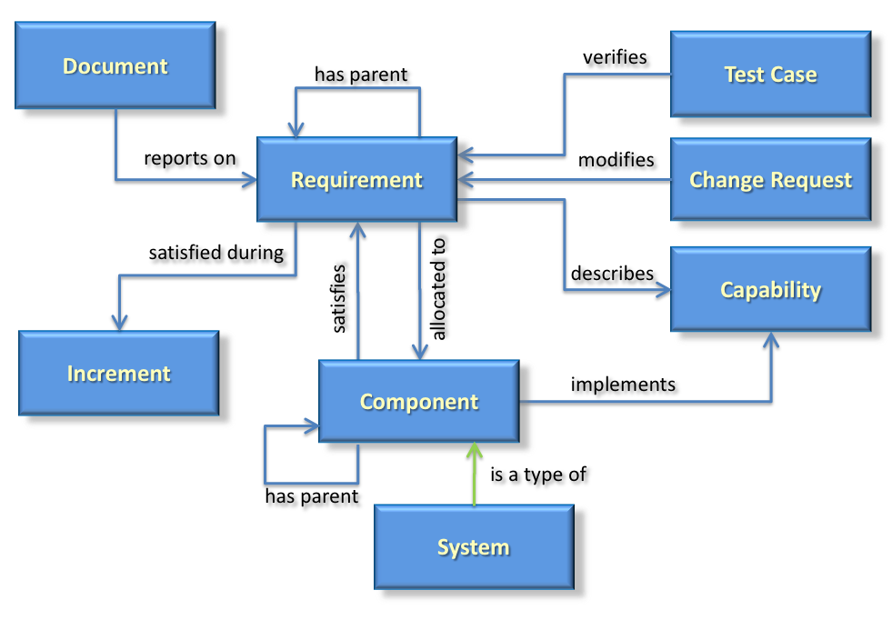
Entities have relationships between one another shown by lines with arrowheads to indicate directionality of the relationship. Relationships show that entities have a correlation or linkage between them. To capture the meaning of that linkage, every relationship needs at least a name to define it, and rules for how the linkage is made.
Consider your relationship to an automobile. You might be the driver of the car which is established when you get into the drivers seat, start it and drive it off. You might very well also be the owner of the car, which is established by the title to the car and kept by a local government entity. You and the car are two very different entities, and have two (or more) very different relationships.
Exploring the Map
Now that we have some basics, let’s look at the SRM map in more detail.
As described above, a well-constructed map of an information territory, or domain, represents well-defined entities with not only a name and perhaps a descriptive definition, but also with a set of attributes necessary to characterize the entity in the particular context. Each of the elements in the SRM needs its own set of attributes. Let’s explore the entity at the center of the SRM, the requirement.
So what is a requirement? According to INCOSE, a requirement is:
-
A condition or capability needed by a user to solve a problem or achieve an objective.
-
A condition or capability that must be met or possessed by a system or system component to satisfy a contract, standard, specification, or other formally imposed documents.
-
A documented representation of a condition or capability as in (1) or (2)
For our purposes, a requirement is most closely like definition 3, the documented representation of 1 and 2. Since it is a defined element of this model, we shall refer to the entity as a «requirement», where the guillemets («») act as a flag that we are talking about a well-defined element of the SRM.
(If you choose to use an indicator of a defined entity in your documentation, you can choose any indicator you like, or no indicator at all. I advocate flagging any reference that has a well-defined meaning to let readers know they’re looking at something using a precise definition, and not a random or ambiguous term.)
Not only does the «requirement» have a definition, it is also characterized by a specific set of attributes that describe the «requirement» and only the «requirement». Here is a look at the attributes of a «requirement» in the SRM:
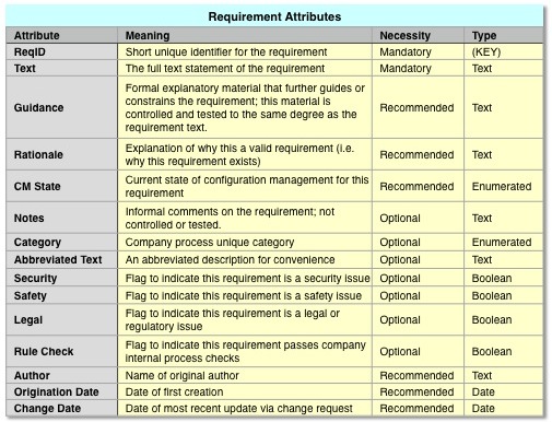
Attributes for a «Requirement» in the SRM
In the context of the SRM (and frankly, in almost all practical contexts) a «requirement» can be characterized with only two required attributes, a unique ID and the text of the user need. (SysML defines exactly these two.) In the SRM there are only 15 requirement attributes defined, and only two are mandatory.
Since the «requirement» entity is at the center of the SRM domain, the next step will be to see how it relates to the other entities in the SRM.
«Requirement» «has parent» «Requirement» Relationship
A set of «requirement»s tends to have a hierarchical organization, so a «requirement» can have a relationship to another «requirement» called its parent, or «has parent». The relationship is shown with a directed arrow. The hierarchy can be discerned by recursively following «has parent» relationships until we find a «requirement» that has no parent «requirement»s.
in a more complex model, the «has parent» relationship might be replaced or complemented with more detailed relationships, such as «decomposes», «disambiguates», or «derived from». The SRM uses the simpler «has parent» relationship.
«Document» «reports on» «Requirement» Relationship
A hierarchical set of requirements is usually represented not in a simple list, but in a document or specification. A «document» is a separate entity from a requirement because a document has a different set of characteristics. Documents will have a formal ID, title, author, revision, multiple sections and subsections and release sensitivity. None of these apply to individual requirements. It makes sense then that a «document» should be stored as a separate entity from a requirement.
This is significantly different from legacy DOORS 9.x implementations, in which requirements and documents are misguidedly mixed together into a confusing morass. (It is possible to separate the two using DOORS 9.x, but that requires the design of the database to differ from the originally intended design of the DOORS application.)
Furthermore, «document»s differ from «requirement»s because «document»s have different methods to operate on and maintain them. Instead, «document» «report on» «requirement»s, or inversely, «requirement»s are «reported on» by «document»s.
Publishing a specification is a process of selecting the «requirement»s from a model based on a query of the requirement allocation to a component, and then building a «document» to organize and report on the selected «requirement»s.
«Requirement» «allocated to» / «satisfies» «Component» Relationships
A «requirement» states what the customer needs, but that need is delivered as a «component» of the overall deliverable system. This is how the SRM ties together the descriptive model of «requirement»s with the structural architecture model of «component»s. A typical business rule maintains that a «requirement» is allocated to exactly one «component». (If it were allocated to more than one, then the «requirement» would be stating more than one goal and needs to be decomposed into multiple requirements.) The inverse relationship says that a «component» satisfies a «requirement». A «component» can satisfy multiple «requirement»s.
A «component» is a separate entity from a «requirement» because it has unique characteristics that describe it as a physical entity. «Component»s will have a unique identifier, a set of functions, a set of constraints, physical characteristics that describe it as a controllable physical item, procurement attributes and others. In addition, «component»s are managed and controlled as configuration items, not as «requirement»s.
«Component» «has parent» «Component» Relationship
The architecture of a system generally is a hierarchical structure of «component»s. Similar to a «requirement», a «component» has a relationship to a parent «component» via the «has-parent» relationship. Traversing the «has-parent» relationship reveals the structural hierarchy.
«System» «is a type of» «Component» Relationship
In the SRM, «requirement»s are «allocated to» «component»s, which allows some flexibility in how a business defines a «component». Since I’m describing a system engineering model, the model needs to have a «system» in it. In the SRM, I show that a «system» is a specific kind of «component» using the relationship «is a type of». In a larger and more useful SE model, the «system» and «component» would have a much more detailed model surrounding them and describing more relationships.
«Requirement» «satisfied during» «Increment» Relationship
In many projects, the development effort will be spread over several phases, or implemented in «increments». A business rule might state that a «requirement» will be «satisfied during» exactly one increment. (If it were «satisfied during» more than one, then the «requirement» would be stating more than one goal and needs to be decomposed into multiple requirements.)
«Test Case» «verifies» «Requirement» Relationship
In order to prove that a «requirement» is met, the «requirement» needs to be tested and verified. A «test case» defines the testing and verification approach and is related to multiple «requirement»s through the «verifies» relationship. A «test case» is a unique entity from a «requirement» not only because it has unique descriptions and goals, but is finalized during a later lifecycle phase of the program, generally after the requirements set has been baselined.
«Change Request» «modifies» «Requirement» Relationship
In order to control changes to a requirements set in an orderly fashion, each «requirement» is generally placed under control of configuration management. A business rule might state that a «change request» is necessary before modifying a «requirement». The «change request» might have attributes that look a lot like the attributes of a «requirement», as well as additional attributes for status and tracking of the request. The «change request» is handled differently from a «requirement» and lacks the other relations of a «requirement». Given these factors, the «change request» is an independent entity in the SRM.
«Requirement» «describes» «Capability» Relationship
A «requirement» states what the customer needs, but ultimately the customer has a specific desired effect the customer wants to see in the end product. That desired effect is captured by a «capability» entity. Typically multiple «requirement»s will «describe» a «capability». This is how the SRM ties together the descriptive model of requirements with the results-driven behavioral model of «capability»s.
«Component» «implements» «Capability» Relationship
Finally, the «components»s of the end product must exhibit well-defined, desired behavior to satisfy the customer. The SRM models this by showing that a «component» «implements» one or more «capability»s. A business rule might allow a «component» to «implement» many «capability»s, but insists that a «capability» be implemented by exactly one «component». (If a «capability» were implemented by multiple «component»s, then the «capability» would need to be decomposed into multiple subcapabilities. The SRM, being simple, does not support this.)
Map Making Lessons
This map is so simple the reader no doubt found multiple deficiencies and inconsistencies between this simple model and their own company’s system engineering approach. Still, this simple example provides a background to learn a few lessons.
One of the first lessons learned is that creating this very simple map, or schema, is a surprisingly tedious process. It was probably even tedious to read it. (Sorry about about that.)
Part of what makes it so tedious is that we feel we already know these entities and relationships. If we knew them so well, they would be written down, wouldn’t they? If everybody knew them by the same exact definition, wouldn’t the system engineering process go much faster and be more accurate? Despite feeling that we know them, almost no one has really taken the time to be explicit with them. (I’m sure a Vitech Core sales representative will chime in here. Feel free to comment.) As a result, when moving from company to company, and even project to project, we waste a lot of time reinterpreting our map for the SE process, and stumbling over minor misconceptions and terminology. SE is a discipline of communication and information management, yet we fail to do that for ourselves.
If your company actually goes to this level of detail, or more, please let me know in the comments. I only encountered one organization in my 35 year career that actually gave this much thought to the engineering process.
Another humorous lesson is that using guillemots is itself tedious, especially in an article that references the underlying entities of a model a lot!
And we’re not done yet. The next lesson to be learned is captured in the final installment of information management in systems engineering. I’ll explore how to use the SRM to satisfy the needs of engineering users.
DISCLAIMER: I am tool agnostic. I am not associated with any tool or vendor, nor do I benefit from any tool sales or stock.
(part 4 coming soon)